Belajar Microkontroller adalah sesuatu hal yang mengasikkan, tetapi kadang-kadang menjadi memusingkan bila tidak ada teman atau buku yang dapat memandu untuk membuat sesuatu.
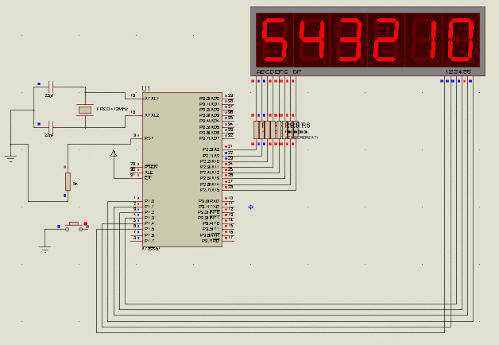
Berikut ini satu buah project kecil yang berkesinambungan, dimulai dari, penampilan angka pada Display 7-segment. Ada 6 digit display yang akan dikendalikan dengan metode Scanning.
Perangkat Pendukung untuk belajar MCS-51 anda butuh Software Simulator, Seperti Proteus dan Mide Assembler Editor & Compiler.
Cara Kerja dan Program Assembler
$ mod51
;============================================================================================
; 6 D I G I T D I S P L A Y 7 S E G M E N T
;--------------------------------------------------------------------------------------------
; Controlled by MCS-51 (Atmel 80C51 )
;--------------------------------------------------------------------------------------------
; By BINSAR SIAGIAN
; Instructor of Electronic Department of TEDC BANDUNG
; www.tedcbandung.com
; binsarid@yahoo.com
;--------------------------------------------------------------------------------------------
;
; Application of a Microcontroller requires an output of 7 segment display,
; to show to the user, about what is in the doing by the application.
; One of the most important part of the Project plan that was my wake up
; is a seven segment display with 6 digits, in order to display the article
; and view HOURS, MINUTES, SECONDS, and calendar (ddmmyy).
;
; This section is the most basic groups of 6 major parts-making Project
; "DIGITAL MUSIC CONTROL BELL". The sections include Digital Clock(Need Display),
; Input Data into RAM (Need Display), calendar Control (Need Display),
; Audio Control Amplifier, Making the Melody and control the Microphone (not Need Display).
;
; I wrote this program in the most simple, so there had seen the re-writing,
; with the intention to be easily traced on the intent and purpose of those commands.
;
; You can change the contents of memory locations in accordance with
; the position letter code location that you saved on buffer locations.
;
;--------------------------------------------------------------------------------------------
; H A P P Y E X P E R I M E N T
;======================================================
Dig0 equ 45h ; This is RAM Addres for Data Display
Dig1 equ 44h ; from Digit-5 to Digit-0
Dig2 equ 43h
Dig3 equ 42h
Dig4 equ 41h
Dig5 equ 40h
org 0000h
ljmp Main ; Preparation to jump from Adress Vector Interrupt
org 0100h
Main: mov Dig0,#0 ; Memory for Digit-5 to Digit-0 gived the Data Numbers
mov Dig1,#1
mov Dig2,#2
mov Dig3,#3
mov Dig4,#4
mov Dig5,#5
MOV DPTR,#KarakterCode ; Pointer for the Karakter Code for Display
Start: MOV A,Dig0 ; to Display Data from Digit-0 to 7 Segment
call Jemput
mov P1, #00000001b
call Delay
mov A,Dig1 ; to Display Data from Digit-1 to 7 Segment
call Jemput
mov P1, #00000010b
call Delay
mov A,Dig2 ; to Display Data from Digit-2 to 7 Segment
call Jemput
mov P1, #00000100b
call Delay
mov A,Dig3 ; to Display Data from Digit-3 to 7 Segment
call Jemput
mov P1, #00001000b
call Delay
mov A,Dig4 ; to Display Data from Digit-4 to 7 Segment
call Jemput
mov P1, #00010000b
call Delay
mov A,Dig5 ; to Display Data from Digit-5 to 7 Segment
call Jemput
mov P1, #00100000b
call Delay
ljmp Start ; Looping to Start as Scanning Display
Delay: mov r1,#100 ; Delay for ON each Display as Scanning Time
loop2: mov r2,#30
loop1: djnz r2,loop1
djnz r1,loop2
mov P1, #00000000b ; This is TRICK to remove Blink Display on Simulator
ret
Jemput:
movc A,@A+DPTR ; Fetch Character Code from Buffer locations
mov P2,A
ret
org 0200h
KarakterCode: db 11000000b ; 0 ; Character Code for Number 0 to 9 and A charakter as HEX Number
wrote as Binary.
db 11111001b ; 1 ; This Binary Number comes from variation of Segment light ON or
OFF
db 10100100b ; 2 ; as a simbol of the number. Not all can be real as Character
but nearly
db 10110000b ; 3 ; simbol can be made by them.
db 10011001b ; 4 ; In the circuit from Port-2 comes output as active Low and
Common Anode control from
db 10010010b ; 5 ; Port-1 High will Display Digit to be Light ON, and display the
Number.
db 10000010b ; 6 ; All Binary number comes from connection of segment
a,b,c,d,e,f,g to the Port-1
db 11111000b ; 7 ; a to P1.0
db 10000000b ; 8 ; b to P1.1
db 10100010b ; 9 ; c to P1.2
db 10001000b ; A ; d to P1.3
; e to P1.4
; f to P1.5
; g to P1.6
; dot to P1.7
END


No comments:
Post a Comment
Silahkan memberikan komentar untuk perbaikan dan diskusi !
Note: Only a member of this blog may post a comment.